Research note · 10 Mar 2025
Which values to choose for gl and gs?
Comparing orbital and spin contributions to calculated M1 strength functions.
The gyromagnetic ratios determine how strongly the nuclear magnetic dipole moment interacts with the electromagnetic field, which directly affects the M1 transition strength. They show up in the operator as
Protons and neutrons have different gyromagnetic ratios. The orbital motion of a charged particle produces a magnetic moment. Since only protons have charge, they alone contribute to the orbital part of the nuclear magnetic moment. The magnetic moment of a moving charge is given by
To compensate for various shortcomings of shell model calculations, like truncations and inert cores, it is possible to set the orbital g-factor for neutron to a non-zero number. This is is done in some cases for the sdpfsdg-mu interaction (like here where it is set to : https://doi.org/10.1103/csx6-6g5k). More commonly, the spin g-factors for protons and neutrons are often “quenched” in shell model calculations, in which case the free values of and for protons and neutrons respectively, are multiplied with a factor that is typically between and depending on the interaction. See the nuclear shell model interaction overview for details.
What we can do is to artificially set the g-factors to zero to see what effect is has on the M1 strength function.
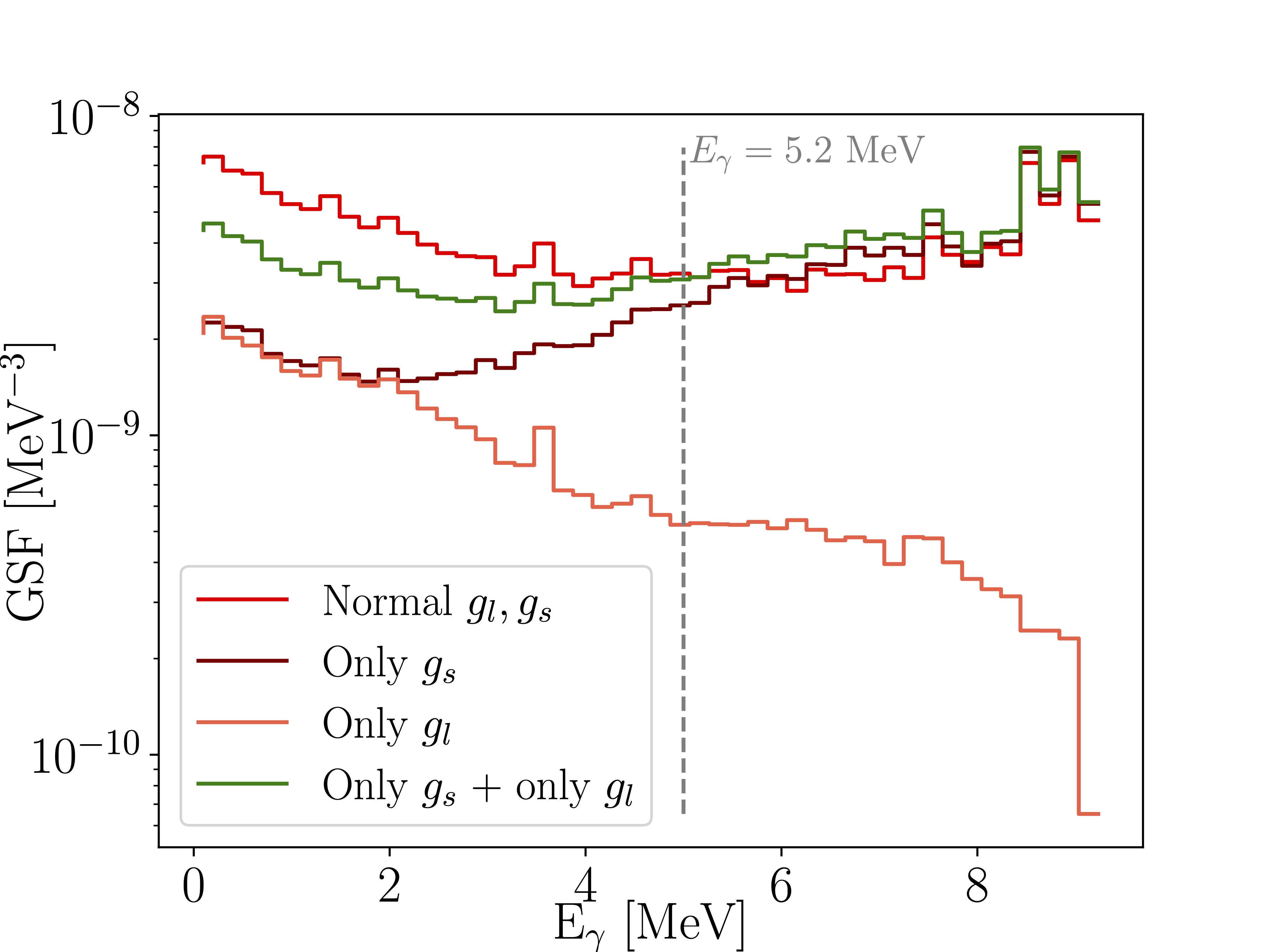
In dark red and in orange we have “only ” and “only ” where I have set and respectively. In the low energy region of approx MeV we see that the and term play almost exactly the same role. As the gamma energy increases past MeV however, we see that the “only ” part is increasingly doing the full duty of producing the M1 strength.
and are vector quantities which means that calculating the and parts separately and them adding them together does not work. That’s because to get the GSF we have to calculate
and expanding that square we get
and dubbing the first term and the second term we get
where the cross-term is the important part. Naively summing is exactly the green line in the figure. From 0 to 5.2 MeV the naive sum underestimates the properly summed M1 strength meaning that there is constructive interference between the and terms that is not included, aka is positive. While beyond MeV it is the opposite.
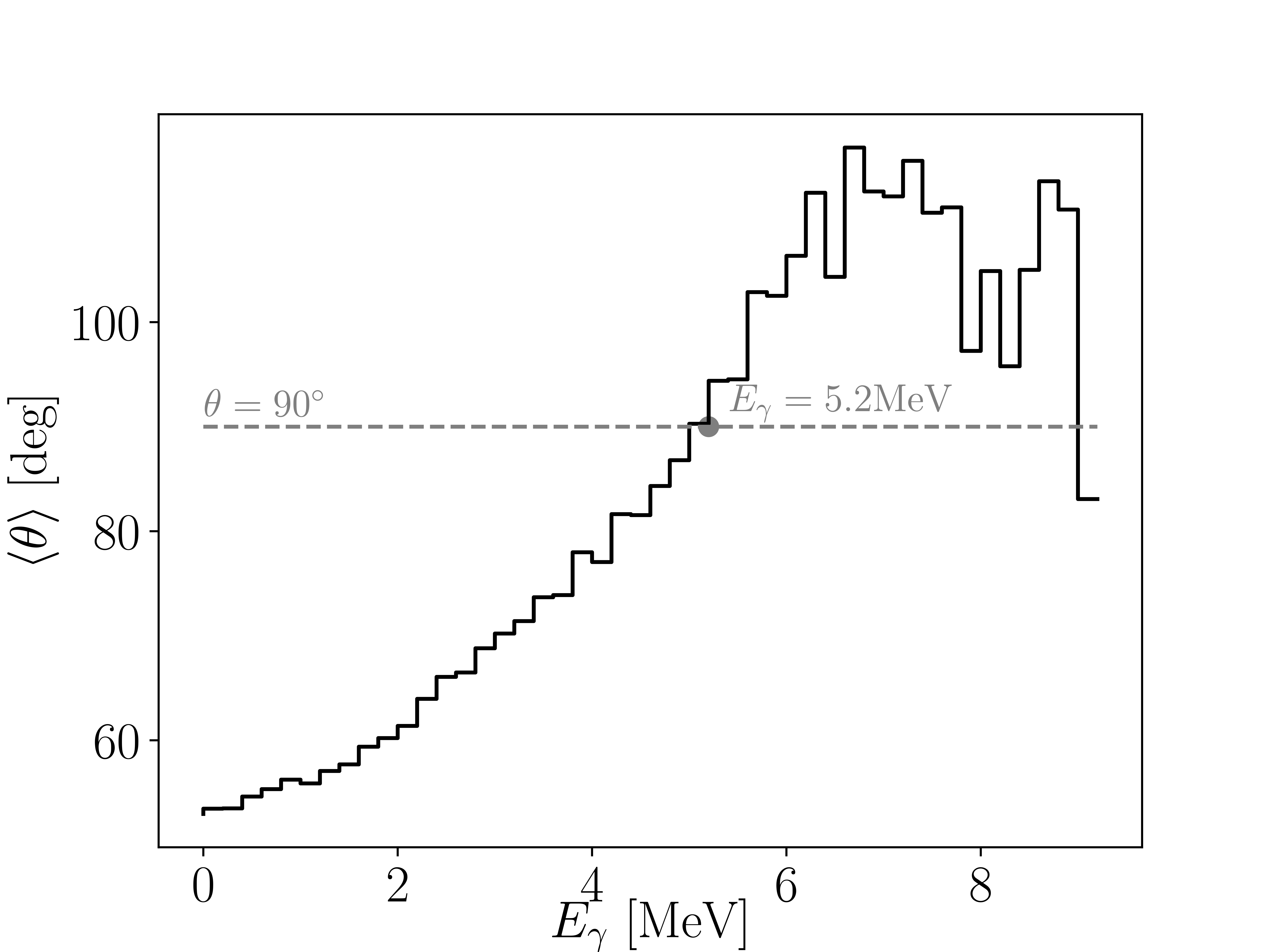
In the figure above I have calculated the average interference angle between and . If you visualise a simple xy-plane with two vectors in it, you can imagine that if the vectors are at 90 degrees their is equal to zero. If the angle is less than 90 then the cross-term is positive aka. constructive interference and vice versa for angles greater than 90.
Discussion
Comments
Comments are public. Anonymous sign-in stores an identity in your browser; basic network metadata is retained for abuse prevention.